|
|
|
|
|
|
|
|
|
|
|
|
|
|
Dyna-Cam Home Page
About Dyna-Cam
magazine articles
Photojourney
MANUFACTURING STARTED BY DYNA-CAM
Torrance, CA., - President, Pat Wilks, announced that 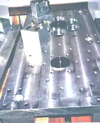 DYNA-CAM Engine Corp. has taken delivery of Haas CNC production
equipment and is performing final machining of the production tooling, fixtures and jigs. The initial production of Dyna-Cam Engines has begun.Initially, Dyna-Cam will do about 75% of the machining of the
major castings and components. The initial production will be about five engines per month. The current CNC machining equipment can build up to 40 engines a month. For many years it was believed that Dyna-Cam
could totally outsource the engine and just assemble, test and sell the engines. But by using total outsourcing, the engines cost more to build than what they could be sold for. Wilks said the last production prototypes
ended up costing over $50,000 to build.
Wilks says, We frequently get asked, 'Why has it taken so long to get the Dyna-Cam engine into production?' which is understandable.
Because if you haven't started an engine manufacturing company yourself, you just cannot have any idea of what it takes.
She said, operating on family investment, it took over five years to complete the installation of the
Dyna-Cam engine into a 4-place Piper aircraft and a speedboat for testing, evaluation, and to complete the necessary market analysis. Then it took another five years and hundreds of meetings to raise enough money to
start production. Using outside vendors to do the machining seemed the most highly recommended and only way to start production. So machining price quotes were requested from every possible source, and for
the first few years we had the initial machining on the prototypes done by outside vendors. But the cost of the machining alone ended up costing over $40,000 per engine and that was an absolute
"show-stopper." Additional investment and financing was not available to build the engines "on spec" with that pricing."
Wilks's partner, Chief of Operations and Engineering, Dennis Palmer, and a couple of other volunteer associates have
now completed intense, accelerated, cad/cam programming and CNC machining training. An SBA loan helped finance the
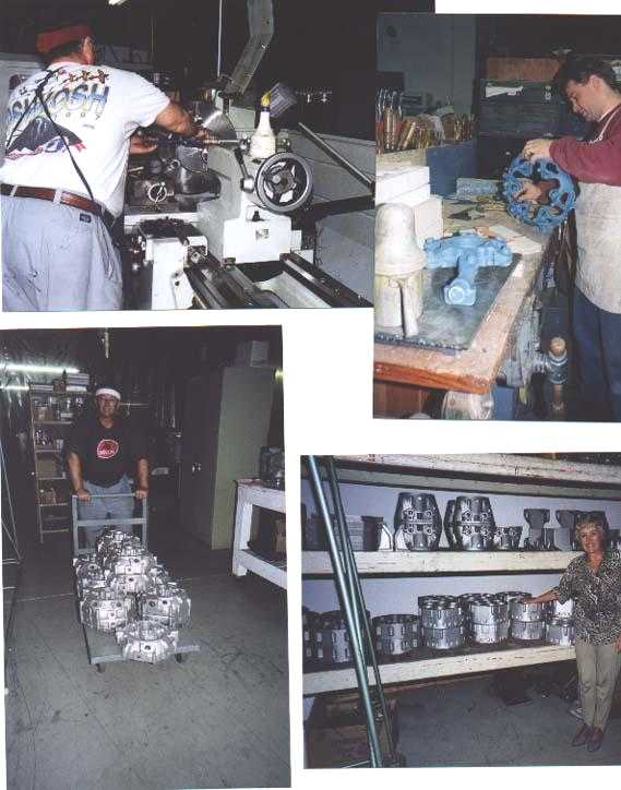
latest state of the art CNC lathe and machining center equipment and allowed us to purchase the first round of castings. The photos show some of the current operations and document what's been going on the last few years.
Contact
FAQs
Mailing List
Site Map
First, all the tooling plates, fixtures and jigs had to be machined with higher precision than is even required on the castings. Those innocent looking holes on the plates above and to the left must be  within .001 of perfect.
The tooling plates are placed on the CNC machining centers
to hold the castings with absolute precision for the machining operations. The plates shown here hold the blocks and heads in various positions for machining. The tooling and fixtures
completed so far would have cost at least $75,000 - $100,000 from an outside vendor .
 Photo to the right shows two round plates
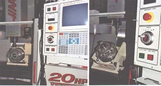
located on the rotary table with the nose cone casting being lowered into position. For machining, the rotary table is placed on the CNC machining center table, as shown in the photos below.
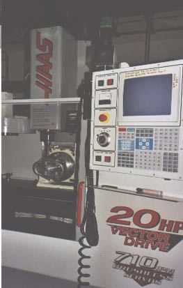
The rotary table can then be tilted forward or back with exact precision to allow machining of the various ports and bosses spaced around the engine at different angles. In the third and fourth photos
the engine head is shown in two different positions on the rotary table.
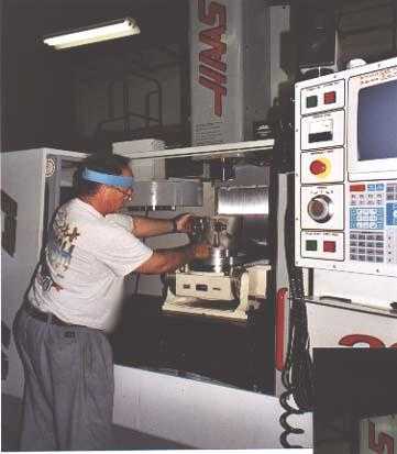
Left - the gear case is being positioned on the rotary table.
Additional photos that follow show Dennis working on the manual lathe, a plastic study model of the head coolant passage being trimmed, and stacks of gear cases, blocks and head castings now delivered and ready for machining. All other phases of engine assembly and testing have already been conducted at Dyna-Cam facilities.
Interested buyers or dealers are invited to contact the company on the web site at http://www.dynacam.com or by calling direct: 310-791-xxxx or FAX:310-791-xxxx.
BACK TO THE TOP NAVIGATION BAR


